SHED SOLAR GENERATOR
With the current unpredictable weather and climate, we continue to have power outages every so often. I decided to take matters into my own hands to create and install my own electricity sources if my home was out of public electricity. I have built a 2500-watt solar generator on and in my shed and backed that up with a 3500-watt gas/ propane generator. I can use either the solar generator or the gasoline/ propane generator to run the furnace, refrigerator, freezer, and a few other low-energy appliances. In this article, I will explain how I set this system up, hoping that I will inspire you to do the same or better. For your awareness, I am not an electrician. I highly encourage you to contact an electrician and your local electrical inspector as you set up this system.
Project description: Solar panels on the shed roof; charging a 24 volts (V) DC (Direct Current), 400 Amp battery bank; a 2500-watt inverter converting the 24 V DC to 120 V AC (alternating current); I wired the AC through an underground PVC (polyvinyl chloride) conduit from the shed to a generator transfer and disconnect switch on the outside of the house;I connected the AC line to an automatic transfer switch in the main house; the power from the automatic transfer switch goes into a 4-space (8-circuit) load center to power the furnace, freezer, refrigerator, and one outlet. I can connect A 3500-watt generator to the transfer/ disconnect switch outside the house.
SAFETY: Don’t take chances. Do not compromise your safety. Do not take shortcuts. Use appropriate safety equipment. Here are some of the safety equipment I used for this project:
Helmet:
Safety glasses:
Work gloves:
Knee pads:
Work boots and socks:
PERMITS: I needed a permit from my county/ city. Not all zones allow solar panels on shed roofs. I drew out my plan to scale as best as I could. I made a detailed description of my plan. I attached the description and sketch of the project to the permit application. I gave my project a name, ‘Shed Solar Generator.’ The shed roof and structure have to be of a certain kind for the solar panels to be permitted on there. The permit application process helped determine if the shed type and zone allowed for the shed solar project. Click here for an example of a rooftop solar permit application form.
Once the county/city approved, I should have applied for an electrical permit right away to access the state electrical inspector for my area. i could have asked the electrical inspector if the gadgets I was planning on using met the state’s electrical safety standards before making any purchases. I did not apply for the electrical permit until the panels were on the roof and approved. When the electrical inspector came over for the first inspection, many of the equipment did not meet the state safety standards. He recommended that I improve the project by switching out the non-compliant parts and adequately ground all components that required grounding. I replaced all the equipment the was not up to the safety standards, and I passed the inspection the second time. Get this right the first time, so you don’t have to repeat anything. Click here for an example of an electrical inspection/ permit application process.
WHY PERMITS: Permits were necessary for my own safety and the safety of my neighbors and family. The inspectors helped me do this home improvement project to my neighbors’ and family’s safety standards.
Tools: I got this project completed with just simple essential tools. When I used a big tool/ machine just once, it was more cost-effective to rent it than to purchase it. I rented the trench digger for four hours to dig the conduit trench.
Hand saw for wood and plastic:
Drill/ driver:
Drill bits:
Bench vise:
Drill/ driver [cordless]:
Ladder:
Tool belt:
Caution buying components: Before the second inspection, I made sure all the parts/ components I used for this solar system were approved by at least one of the USA or Canada national testing laboratories, of which UL is the most common. Click here to see the approved national testing laboratories. The labeling of at least one of these laboratories must be on the product. When unsure of a component, I sent a photo or weblink to the regional electrical inspect, asking him if the product was acceptable.
Solar panels: I took a photo of the labeling on the back of the solar panels before mounting them. The electrical inspector needed proof that the panels were approved by at least one of the Nationally Recognized Testing Laboratories (NRTL). I reinforced the shed roof from the inside of the shade to improve its ability to hold the weight of the panels and my weight while on top of the roof. The panels had to withstand winds of at least 80 MPH (Miles Per Hour). I strategically added a rafter to ensure all the mounting bolts bolted into rafters. I used some anchoring metal plates to add the extra rafters. Here are some solar panels:
SCREWS: I used the 3-inch screws to attach the panels to the roof. These went deeper into the rafters, providing more robust and secure attachments.
SEALANT: I put some sealant between the mounting brackets and the roof before ultimately tightening the brackets down to the roof to prevent any water leaks.
WIRING THE PANELS: I created three arrays. The south array has three 250-watt, 37-volt solar panels wired in series to make a total of 750 watts & a maximum voltage of 111. The north array has three 250-watt, 37-volt solar panels wired in series to make a total of 750 watts & a maximum voltage of 111. The center array has four 100-watt, 18-volt solar panels wired in series to make a total of 400 watts and a maximum voltage of 72. I connected each array to its charge control for a total of three charge controllers. Since the wires are not supposed to touch the roof, in some sections, I ran the wiring in a customized short conduit to prevent contact with the roof surface. I also added extensions so the wires could reach the control panel inside of the shed.
CONDUIT INTO THE SHED: To get the wiring from the solar panels to the inside of the shed, I used a hole saw to make a hole in the roof. I then attached a pipe fitting base underneath the roof while aligning the two holes. I connected that to a short PVC conduit and service entrance cap and ran the wires in.
Wiring in the shed: Once the wires are off the roof, they must be in a conduit or box; no wires should be visible on the outside. I attached a junction box to the base of the conduit base. I then attached three conduits to the junction box to run each array’s wiring to its specific charge controller and disconnect switch.
DISCONNECT SWITCHES: I had the lines stop at another junction box to connect to disconnect switches before going into the charge controllers. It is convenient to be able to turn off the arrays just by flipping a button instead of disconnecting wires.
CHARGE CONTROLLERS: I then connect the arrays to the charge controllers. I inserted a 30-amp fuse between each array and the charge controller.
Knockouts: When the knockouts are too big for the conduit or too small, I customized the hole size to fit by drilling my own hole through the existing knockout but doing so very gently, so the current knockout did not fall out. Otherwise, when the knockout came out, I covered it with a knockout cover and drilled the hole in the center of the knockout cover.
COMBINER BOX: I then combined all the current from the charge controllers into one in the combiner box, with each array/ controller electricity going through its circuit breaker before the combination. Also, here is where the current from the batteries meets the current from the solar arrays. Additionally, the loads (24 V DC to the automatic transfer switch and the 24 V DC to the inverter) start here in the combiner box.
DISCONNECT: I installed a disconnect switch between the batteries and the combiner box and between the load and the combiner box.
BATTERY BANK: My battery bank consists of eight batteries: Each battery is 12 V DC and 100 Amps. I wired the batteries in series of twos for a 24-volts DC and 400 amp battery bank. I housed the batteries in two metal enclosures for safety. Here are all the components of the battery bank:
The larger battery enclosure fits six batteries in three levels. In comparison, the smaller one holds four batteries in two groups. The fuse is between the batteries and the load. I added some insulation boards to the inside of the battery enclosures to keep the batteries warmer in the winter.
INVERTER: I installed a 2500-watt inverter to run the furnace, refrigerator, and freezer. The inverter converts the battery 24-volt DC electricity into 120-volt AC electricity. I inserted a 150 amp DC circuit breaker between the battery bank and the inverter.
GROUNDING: I grounded all the solar panels, metal electrical boxes/ enclosures, and the inverter.
Conduit power lines: Two 12 AWG (American Wire Gauge) wires are in the conduit from the shed to the house. One wire is for the 120 volts of AC electricity from the inverter. At the same time, the second carries 24-volt DC power from the batteries to the automatic transfer switch. The 24-volts are needed for the first automatic transfer switch to detect battery voltage to turn the inverter load on/off at set voltages to prevent over-discharging the batteries. Both wires meet in a junction box before taking off from the shed. The 24-volt DC wire runs through a 20-amp fuse at the junction box.
UNDERGROUND CONDUIT: I ran two 12/2 AWG from the shed through the conduit to the AC disconnect switch outside the house. One carries a 24-volt DC while the other is a 120-volt AC. The 24-volt DC disconnects in the shed and runs through the disconnect out of the house straight into the first automatic transfer switch for DC voltage monitoring. The 120-volt line is re-wired at the disconnect/ transfer switch outside of the house. The transfer/ disconnect switch can turn off all AC load for any maintenance or switch from solar power to generator power. This switch allows for plugging in a gasoline/ dual-fuel generator. The conduit is ¾ inch in diameter.
AC DISCONNECT: I wired the solar AC as the ‘line’ to the disconnect/ solar/ generator switch. Wiring this switch is very easy, with all the instructions written on the door. The switch I used is the Reliance Controls Model CSR301 with three prongs for the gasoline/ dual-fuel generator hookup. I ordered it directly from Reliance Controls because I couldn’t find it on amazon. It looks identical to this one, only that this one has four instead of three prongs:
TOOLS: I needed a few simple tools. I used the saw to cut the PVC pipe. I used a specialized drill bit to drill a hole into the wall to create an entrance for the conduit from the outside to the inside of the house.
Junction: The conduit arrives at a junction box within the house.
AUTOMATIC TRANSFER SWITCH 1: The first automatic transfer switch receives the 24-volt DC line to monitor battery voltage, to turn on/ off the AC load at set battery voltages. This switch is essential to protect the batteries from over-discharging. To make this switch safe, I housed it in an electrical box. I modified the box’s cover to access the switch, screen, and buttons. I folded the cutouts inwards to prevent the accidental touching of wires underneath. I also installed a grounding bar inside of the box. This switch also receives the AC power from the solar generator.
AUTOMATIC TRANSFER SWITCH 2: AC power from the first Automatic Transfer Switch (ATS) goes into the second ATS. The second ATS gets power from the solar/ generator and public electricity. The second ATS uses solar/ generator electricity and only switches over to public electricity when solar/ generator is unavailable. This second ATS cannot monitor the batteries. With the two automatic transfer switches, the transfer of electricity between solar/ generator and public electricity is so intuitive and effortless that the whole system is immediately on autopilot once correctly set up and turned on.
PUBLIC POWER TO ATS 2: I installed a 20-Amp circuit breaker in the main public power load center for the line to the ATS 2. I used 10/2 wire for all AC power from the disconnect switch outside the house through ATS 1 and ATS 2 and from ATS 2 to the solar/ generator load center. I ensured I turned off the main switch before installing this circuit breaker.
Load Center: From ATS 2, the power goes into the load center to power the furnace, refrigerator, freezer, and outlet. Whichever power ATS 2 decides to power the loads with goes through the load center first then to the loads.
FURNACE TRANSFER SWITCH: I used the EZ Generator Switch with slight modifications in the wiring. Instead of having the solar/ generator plugged in from the front of the switch, I made it more convenient by wiring it from the back, getting the power from the load center. I removed the front plugin provision and covered the hole with an improvised fitting metal plate. I rerouted the furnace public electricity through the EZ generator switch as per the installation instructions. I also added an extra junction box to accommodate the additional wiring from the EZ Generator Switch. All grounding is in the load center on to the grounding bar I installed in the load center.
REFRIGERATOR AND FREEZER LINES: I then ran two extra power lines: one to the freezer and the other to the refrigerator. I used 14/2 wire and GFCI (Ground-fault circuit interrupter) outlets.
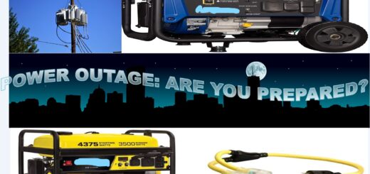
GASOLINE/ DUAL-POWER GENERATOR: Because the outside AC disconnect switch has a generator plugin, I bought a 3500-watt generator for backup in case of any power outage. When necessary, I will simply plug in the generator and flip the switch to the generator to run the four loads (furnace, refrigerator, freezer, and one outlet) from the solar/ generator load center. I chose the dual-fuel generator to double the run time switching to the next fuel when the primary fuel runs out. I can also save money by using the more cost-effective fuel type.
The fun in all of this is doing it yourself (DIY). It is so rewarding to know that somehow you are saving the environment by tapping into the sun’s free energy whenever it’s available. I also gained much confidence in doing most of the electrical work at our home independently. I am saving money by running some of the appliances with solar energy and working on multiple electrical home improvement/ maintenance projects on my own. Setting up this project, I never had to ask the public electricity company for permission since this is not a grid-tied system. I hope this inspires you to do the same project at your home to save the environment and lower your electricity bill by tapping into the free sunlight.
______ This article contains affiliate links. Follow manufacturer/ seller instructions. ___________